No, But Why? - Configuring OSPF on Three Cisco Routers
A tutorial that provides steps on using GNS3 to converge a network by configuring three virtual Cisco Routers with a single OSPF area.
Published: Monday, March 21st, 2022
A tutorial that provides steps on using GNS3 to converge a network by configuring three virtual Cisco Routers with a single OSPF area.
Published: Monday, March 21st, 2022
This tutorial describes the process of setting up a virtual network of Cisco routers on GNS3. The end-state will be a converged network using OSPF and IPv4.
- Staging the Virtual Devices
- Planning the Network
- Configuring Network Addressing
- Setting up OSPF Areas
- Network Convergence
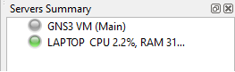
To start, we'll fire up GNS3 and make sure it's ready for building our lab environment. If you're using the GNS3 VM, wait until the VM server indicator goes green in the right-hand pane of the main window. If you're not using the VM, make sure your local machine indicator has turned green. Installing and configuring GNS3 was covered in a previous tutorial that can be found here: https://nobutwhy.com/tutorials/install-and-configure-gns3/
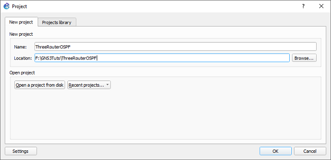
Next up, start a new GNS3 Project. Every project is stored as a collection of files on the device where your GNS3 server is located. If you're using the local built-in GNS3 server, the files will be on your local hard drive. If you're using the GNS3 VM, the files are stored with the VM. Note, this means that you won't be able to access projects on the VM if that virtual machine gets destroyed or corrupted.

With a new project opened, now it's time to drag our devices onto the network map stage. Just click on the left-side router icon, scroll through your list of available devices, and drag the appropriate device model onto the empty staging area. Note, for this tutorial we're using a Cisco 7200 Image. However, you can achieve similar results with open-source systems like FRR. All we really need is a device that can perform Layer Three routing using the OSPF protocol. If you don't have a router setup, refer to the aforementioned setup tutorial to get those steps.
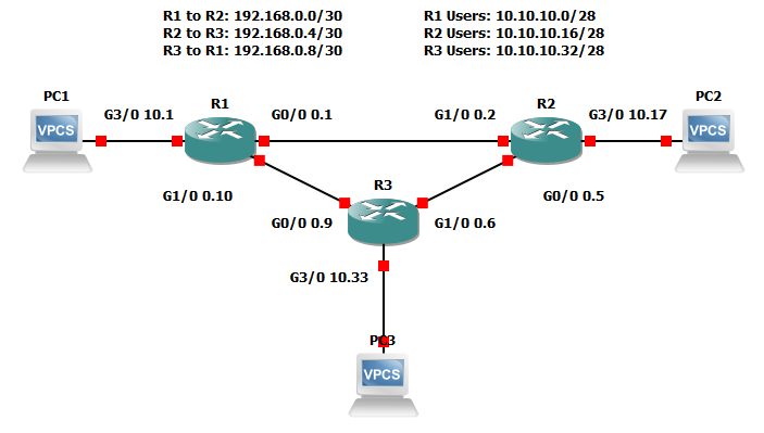
For this project, I've chosen to go in clockwise-order when connecting each system. So: R1 to R2, then R2 to R3, and then R3 to R1. While following this order, I'll use a low-to-high interface connection pattern. The traffic source will be a low number (e.g. G0/0), and the traffic destination will be a higher number (G1/0). In my setup, each router has ports G0/0, G1/0, G2/0, and so-on until G6/0. I create a virtual cable connecting R1 G0/0 to R2 G1/0. Of course, modern Ethernet connections can send traffic in both directions; they're bidirectional and full-duplex. However, high-to-low connection ordering still makes for easier monitoring, troubleshooting, referencing. Note, GNS3 connections will show red (disconnected) until you activate device power.
This kind of connectivity method situates the routers into a ring topology. This means that the devices form a sort of circular data path. The information flows from one machine to the next, and one failed device may cause a failure further down this ring. Each device is dependent on the system connected before or after itself. For more-robust networks, we usually want to build in more redundancy. That means adding secondary connections to another device, or we could add alternate connections using external organizations or different device types. However, those considerations are outside of the scope of this tutorial.
To take a quick step back, a real-world process should include a full implementation plan before we configure any new devices. We should have a plan for where devices will be placed, how they'll be connected, and how the additions will affect traffic flow. Additionally, we'll need to plan out our logical connections and addressing scheme. Being that this is an imaginary simulated solution, we'll focus entirely on that last point. Adding to that, I'll explain the decisions I'm making, but I won't go into detail on things like calculating addressing, physical cabling considerations, or choosing a routing protocol.
First, let's pretend that each router only supports 10 users. For simplicity, assume that all users are connected directly to the router. That creates two hard requirements: create networks for each device-to-device connection, and create networks for each user network. Device-to-device networks have to provide just enough addresses for the interconnected systems. Network IDs and broadcast addresses mean we need a subnetwork with a total length of four. Using CIDR notation, we know that a /30 provides four total and two usable IPv4 addresses. For the purpose of this lab, we'll use the 192.168.0.0/24 private network. Starting at 0.0, the three router-to-router networks will be 0.0/30, 0.4/30, and 0.8/30. That takes care of our router-to-router connectivity.
Next, we must calculate network sizing for the ten users on each router. Using CIDR notation, a slash 28 will give us 16 total IPs and 14 usable. For this lab, let's use the private range 10.10.10.0/24 for our user nets. Starting at 10.0, we'll have 10.0/28, 10.16/28, and 10.32/28. As a side note, don't worry too much if addressing and subnetting is alien to you. The details of calculating these numbers aren't necessary for this tutorial. Just keep in mind that network sizes should be allocated based on user requirements. In the case of IPv6-while it has billions of addresses-it's still useful to segregate networks based on types of traffic, privacy requirements, or for security reasons.
Now that we have an addressing plan, we can apply those addresses to the devices. This is a pretty straightforward process: console into the device, enable configuration mode, select the interface to configure, and then set the IP address of that interface. On a Cisco device, you'll have to use the command configure terminal to start configuration mode. Then, selecting the interface's configuration mode is completed by typing interface <interface type, e.g. GigabitEthernet> <module>/<slot>/<interface number>. Finally, add the IP address with the ip address <IP address> <subnet mask> command. In many cases, you'll also have to enable the interface with the no shutdown command. For this lab, those commands would look like this for Router 1, Interace GigabitEthernet 0/0:
config t*
interface g0/0
ip address 192.168.0.1 255.255.255.252
no shut
*Side note, most commands can be shortened down to about three or four letters for efficiency. In some cases, there's another command that matches the same letters you've typed, and for those you will have to type more than the barest amount. The TAB key can also be used for autocompletion. If multiple commands show up when you hit TAB, that means the device found multiple matches against what was typed so far.
For every other interface, we'll use the exact same process. Console into the router, enter configuration mode, and set the interface IP with the same commands. All that will change is the IP itself and the subnet mask to match our addressing schematic from earlier. Even the user networks aren't treated any differently here. We just have a different address supernet and a different network size identified with the subnet. This doesn't change even if there were a switch between the computers or the routers. Easy, though a bit repetitive. Of course, all of this can be scripted out, but that's a topic for another tutorial.
Before we get into configuring OSPF, it's important to consider the need for a routing protocol in the first place. At the core of it, routing is a process of directing traffic to the appropriate destination. It should be emphasized that routing is not about creating a map or defining the purposes of traffic. Routing can be used to assist with these functions, but all it really does is direct traffic. It's the person with a flag directing traffic on a busy street. All a router does is point in the immediate direction you need to go, and it often has no idea where traffic needs to go after itself.
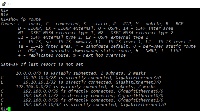
With that in mind, consider the default state of a router without configured routes. The command show ip route can be used to show a Cisco router's IPv4 routes. Reference the figure above, this is a limited table at the start. It only has two supernetworks: the 10.10.10.0/8 net and the 192.168.0.0/24 net. That's all we configured on the device's interfaces. So, the router only "knows" how to direct traffic to the networks we explicitly defined. Every time we define networks on a router's interfaces, it's programmed to send traffic to those destination networks out those defined interfaces. So, a router has to be configured on how to direct traffic elsewhere. This could be accomplished by using staticly-defined routes. These could be individual directions pointing traffic out each specific interface for each specific destination. However, that would get complicated quickly, and it's not very dynamic. If one of your destinations goes down, the router will still send traffic no matter what. Dynamic routing protocols help avoid both those complications and that unresponsiveness.
For this lab, the dynamic protocol of choice is OSPF (open shortest path first). It's a well-supported protocol that has been used for decades. That makes it well-documented and pretty dependable. It's also (usually) easy to configure, but that can depend on the hardware or software implementation. To start OSPF on a Cisco device, we have to accomplish three main tasks: initialize an OSPF process, advertise specific networks, and add interfaces to the OSPF process. For many Cisco devices, that only really takes two steps: create an OSPF process, and advertise the networks. By default, a Cisco device will choose the highest IP configured on the device for its OSPF router ID. Also by default, a Cisco device will add interfaces into OSPF if they have IPs that match the advertised networks. Because of that, setting up OSPF might be as simple as:
config t
router ospf 123 (router ospf <Process ID>)
network 192.168.0.0 0.0.0.255* area 0 (network <Network ID> <wildcard mask> area <Area Number>)
network 10.10.10.0 0.0.0.255 area 0
*Note the use of a wildcard mask rather that a subnet mask. This can be found by subtracting 255 from each octet of the subnet mask (e.g. 255 - 240 = 15).
This actually works fine and could be copy-pasted for the whole lab. Task complete, right? The network statements instruct the router to advertise any matching networks, and the matching interfaces start sending OSPF messages to neighbor with other routers. There aren't even any outright problems with this configuration for a network like this. We're only using private IPs, and its a virtual lab. However, this changes on complex networks or with live public IPs. In those cases, the network statements should be fine-tuned and very specific. It is absolutely necessary to create networks that are reliable for both users and for interactions between larger networks. That reliability is accomplished by making specific, intelligent choices for network paths. So, a best business practice is to define routing network statements that are no larger than necessary. We don't want to risk sending traffic down the wrong path or causing something like a routing loop.
With all that in mind, let's modify our OSPF configuration to meet the requirement of specificity. For each router, we'll only add network statements that exactly match the assigned IPs for each interface. At that, let's also touch on the Process ID and Area assignments. A process ID is just a locally-relevant ID number; its like a label to differentiate when you have multiple OSPF processes. So, use whatever number you want, though reusing process IDs that share networks does make for easier troubleshooting and verification. For the OSPF Area, the short of it is that Area 0 will accept and share its networks with any other OSPF router. You can change that number to anything else, but then the area will only share within routers from its own area without adding additional commands. All that said, here's our OSPF configuration for R1:
config t
router ospf 123
network 192.168.0.0 0.0.0.3 area 0
network 192.168.0.8 0.0.0.3 area 0
network 10.10.10.0 0.0.0.15 area 0
As can be seen, this is still pretty straightforward. We don't explicity define our router ID, and we're not doing anything special with assigning interfaces. Again, there's nothing wrong with this setup. This is perfectly functional and can be replicated on every other router. Take the networks assigned to each interface for each router, and define those network statements to fit the assigned network. In doing that, we also accomplish some of OSPFs requirements for creating a neighborship. Networks have to match between devices, and we have to send OSPF packets out the interfaces that are connected to the routers we'll neighbor with.
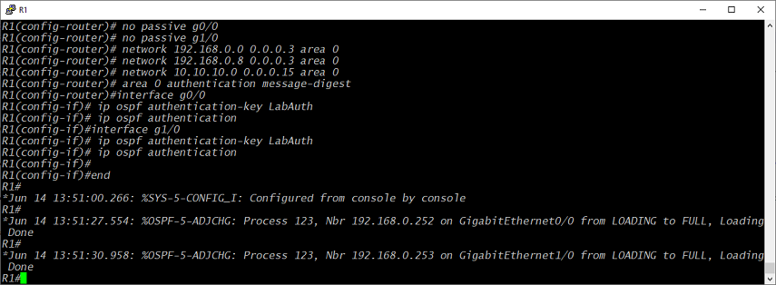
So, the default behavior wraps that up into the router's basic function. However, again, we may want to add some limitations and be explicit. First, we'll add in a router-id statement to make sure we're using the interface we want it to use. That guarantees that an IP change won't disrupt anything. Also, in many cases, you don't want to advertise out of every interface. For that, we'd use the command passive-interface default. Then, we would add in each interface that should send OSPF packets. On R1, that would be G0/0 and G1/0. G3/0 doesn't have a router on the other side, so we don't need to send OSPF packets that way. This reduces network noise and can help increase security. We don't necessarily want to advertise all our routes and OSPF details to just anyone on the line. However, just in case the routers goes through a switch, or the traffic gets intercepted somehow, we'll also add some authentication requirements between routers. That also helps prevent inaccurate or malicious routes from being injected into the network.
config t
interface L0*
ip addr 192.168.0.251 255.255.255.255
router ospf 123
router-id 192.168.0.251
passive-interface default
no passive g0/0
no passive g1/0
network 192.168.0.0 0.0.0.3 area 0
network 192.168.0.8 0.0.0.3 area 0
network 10.10.10.0 0.0.0.15 area 0
area 0 authentication
interface g0/0
ip ospf authentication-key LabAuth
ip ospf authentication
interface g1/0
ip ospf authentication-key LabAuth
ip ospf authentication
*I've added a Loopback0 interface here, but this isn't an absolute requirement. You could use any interface's IP as your router-id. However, a Loopback interface won't go down if one of your neighboring routers gets disconnected. A loopback makes it more likely that your router-id won't be affected by individual connection failures.
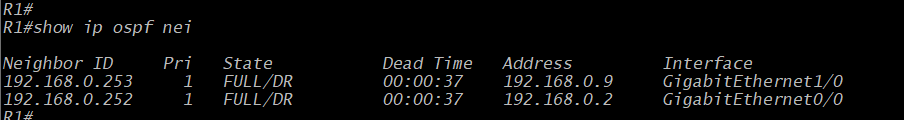
So, after replicating the same steps on all three routers, the network will arrive at a "converged" state. All devices on the network will have reachability to all of the destinations they should have access to. The routers will all have shared their routing tables and have full neighborship with the other routers. One easy way to verify this is to send a quick ICMP Echo to some remote destination. Can you ping the target? If yes, your network is probably converged. Of course, we should also verify with each device by using commands like show ip ospf neighbor and show ip route. Shown above, we can see the results of that first command. R1 has a neighbor with R2, or 192.168.0.252, and R3 at 192.168.0.253.
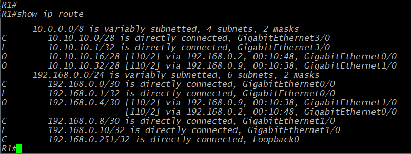
From the show ip route command, we see some extra networks in comparison to the first time we issued that command. We still have our two supernets, but now we've also got some subnets with "O" labels on the left side of the output. These Os mean that the route was learned via OSPF. These are indirectly-learned routes, two for the user networks on other routers and one for the remote router network between R2 and R3.
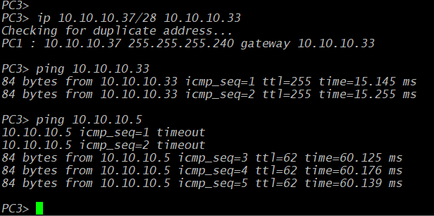
Of course, setting up the network backbone isn't really the point of any of our configurations. The backbone is really there to provide user connectivity. So, a full network test should also include validation and verification from the user's perspective. In GNS3, we can perform this step using the Virtual PCs (VPCs) that come as one of the program's default network objects. If you double-click on one, it'll open a console, and then you can add an IP address with the ip <address>/<CIDR> <gateway> command. So for PC3, we could set it with ip 10.10.10.37/28 10.10.10.33. Then we test reachability from that PC to several destinations across the network.
After all that planning, configuring, and testing, the network is good to go. We've implemented OSPF in an IPv4 environment using GNS3 and some virtual Cisco routers. From the completion of this lab, some next steps might be to implement IPv6 alongside the rest of the network, or maybe redo the same network with OSPFv3 or another routing protocol like BGP. Most of the concepts of OSPF will be repeated in any routing protocols commands and capabilities, but it's good to get a feel for how different protocols work when considering both their syntax and operational responsiveness. Other than that, labs like this can always be added to-more devices (virtual firewalls), more complexity (tunnels), or even hook it up to a real network (cloud interfaces). Hopefully, this was a useful stepping stone toward something more. Cheers.